
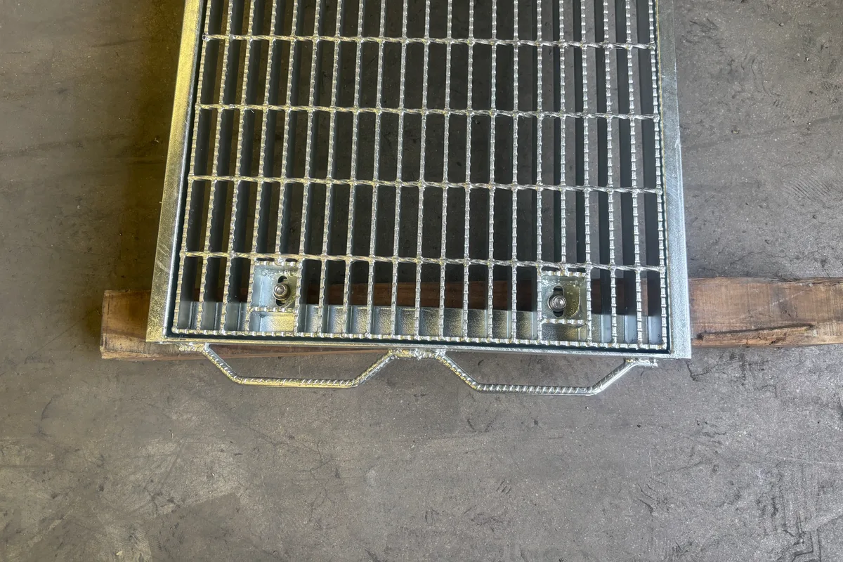
Product and selection guide
Custom Framed Trench Cover Grating: specification overview
A custom framed trench cover is coordinated from the civil opening outward. The opening size, frame outside size and removable grate size are different dimensions and should each be shown. The drawing also needs the top elevation, bearing seat and the relationship to concrete, paving or floor finish.
Panelization should balance clear support, access and practical handling. Special corners, changes in width, outlets and obstructions are best resolved on a plan with numbered panels rather than by a single overall dimension.
Angle-frame and edge details
Include this detail in your drawing or enquiry for an accurate quotation.
Lifting, hinging or fastening requirements
Include this detail in your drawing or enquiry for an accurate quotation.
Straight, corner and special opening layouts
Include this detail in your drawing or enquiry for an accurate quotation.
Fabrication reviewed against customer drawings
Include this detail in your drawing or enquiry for an accurate quotation.
Framed opening dimension schedule
| Drawing code | Dimension / detail | What to confirm |
|---|---|---|
| A | Clear trench or pit opening | Width × length and site tolerance. |
| B | Clear unsupported span | Distance between effective bearing points. |
| C | Frame outside dimension | Coordination with recess, concrete or floor edge. |
| D | Bearing seat | Width, continuity and permitted gap. |
| E | Finished top level | Flush, recessed or raised relationship to the floor. |
| F | Panel size and joints | Panel numbering, joint position and removal sequence. |
| G | Frame section / anchorage | Section orientation, anchors and embedment detail. |
| H | Access hardware | Lift points, hinges, locks, bolts or clips if required. |
Fabrication details that belong on the drawing
- Bearing-bar direction and supported ends
- Load-carrying band versus trim band
- Corners, mitres, curves, outlets and penetrations
- Hinge axis and opening clearance where hinged access is required
- Lifting method and intended panel handling
- Reference datum and installation tolerance
Before production
A reviewed drawing should identify the frame and grate as matched parts, with panel marks and quantities. Field dimensions are especially important for replacement covers or existing trenches where nominal civil dimensions may differ from the actual opening.
Custom Framed Trench Cover Grating FAQ
Which dimension should I use for quotation?
Provide the clear opening and frame detail as well as any required overall size; do not provide only one undifferentiated length and width.
Can irregular openings be discussed?
Yes. Send a plan, dimensions and photos. Feasibility, joints and fabrication method must be confirmed before quotation.
Why number the panels?
Panel marks connect the fabrication drawing, installation position, packing and future removal sequence.
Technical references
Standards and terminology
- YB/T 4001.1-2019 — length, width, span and banding terminology
- Nucor and Grating Pacific catalogs — common fabrication-detail reference
State the applicable standard, edition and acceptance criteria in your enquiry. The quotation and drawing identify the agreed product configuration.
Order and drawing information
Provide dimensions, load conditions, material, finish, quantity and the applicable standard with your enquiry. The agreed details are recorded in the quotation and production drawing.
Read the cover and opening dimensions separately
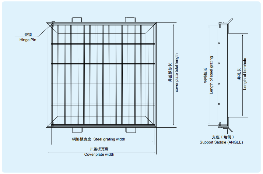
A framed cover drawing should distinguish the civil opening from the fabricated assembly. The diagram below labels the cover plate's overall width and length, the steel grating width and length within it, and the borehole or trench opening length. Those measurements describe different boundaries; substituting one for another can change the bearing seat and installation fit.
| Drawing label | What to measure or confirm | Why it matters |
|---|---|---|
| Cover plate width and total length | Outside dimensions of the fabricated cover assembly. | Coordinates the cover with the recess and finished floor level. |
| Steel grating width and length | Dimensions of the grating panel inside the cover assembly. | Sets the panel layout, edges and bearing-bar direction. |
| Borehole or trench opening length | Clear civil opening between the supporting edges; also provide its clear width. | Determines the unsupported opening to be covered. |
| Support saddle / angle | Angle size, orientation, continuous bearing width and fixing method. | Defines how the cover transfers load into its support. |
| Hinge pin and handles | Whether hinged or lift-out access is needed; pin position, swing direction and handle location. | Preserves opening clearance and a practical removal method. |
Coordinate the frame before fabrication
The side view shows the cover sitting on an angle support beside the opening. Confirm which edges carry load, the bearing width on each edge, the frame's fixing to the surrounding structure and the required top level. A hinge or lifting handle is an access feature, not a substitute for the structural support and restraint details.
For an existing trench, provide measured site dimensions at several points and photographs of the bearing ledge. For a new installation, mark the concrete opening, outside frame size, grate insert size, finished level and panel swing or lift-out clearance on one drawing. Include traffic and wheel-load information where vehicles may cross the cover.
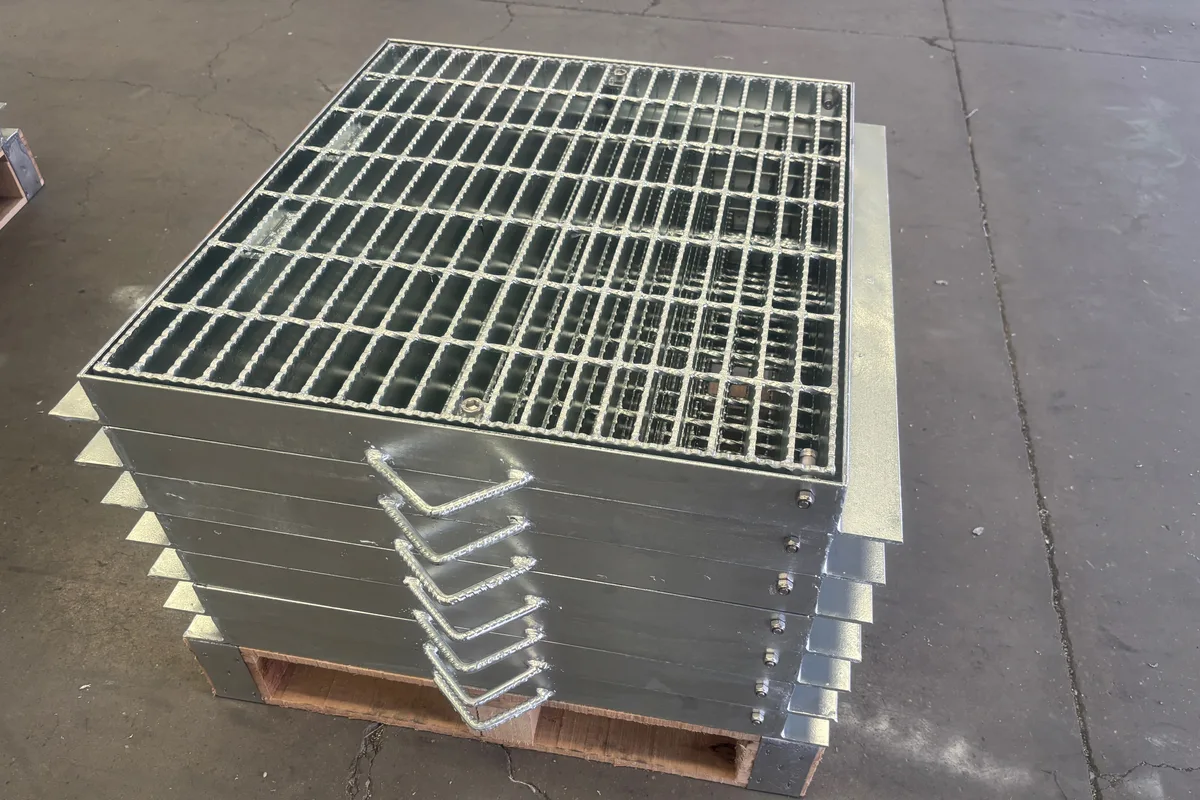
See the trench cover selection guide for the opening, support and traffic details to send with an enquiry, or send your drawing for review.